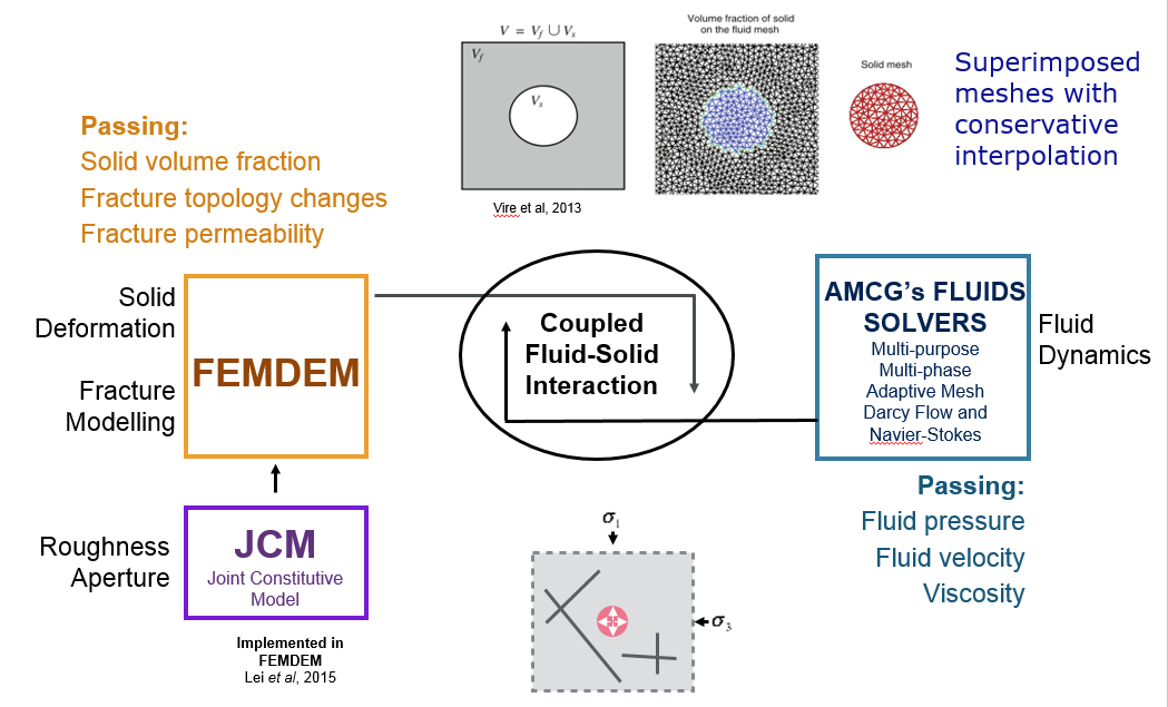
The immersed body method is employed which solves two separate sets of governing equations for the solid and the fluid, and the iterative coupling is achieved through conservative mesh interpolation using the “supermesh” method O’Farrell et al (2013). The schematic figure below highlights the generic coupling methodology in the context of geomechanics showing the inclusion of a Joint Constitutive Model (JCM) combined with the solids solver. The coupled model enables fluid driven fracture from well bores with nearby pre-existing discontinuities to be modelled. In-situ stress affecting the fractured and fracturing porous media and flow in matrix and fracture is captured.The same coupling methodology is shown below, applied to a validation study where results are compared with inertia-dominated flows observed in a turbulent flow solid-fluid experiment.
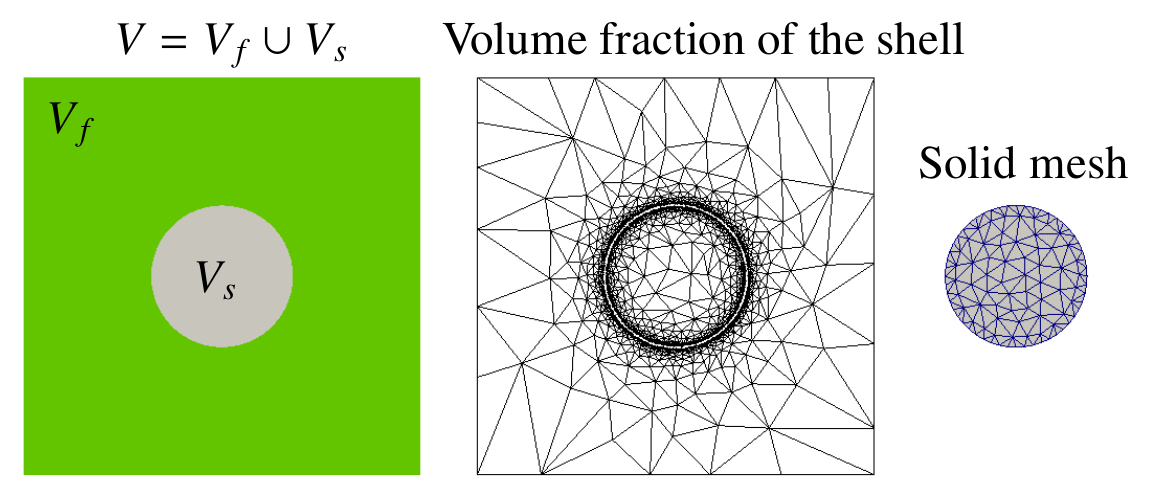
An immersed-body method was developed to model fluid-structure interaction for multiphase viscous flows. It does this by coupling a finite element multiphase fluid model (there are several to chose from depending on and whether porous media and Darcy flow is applicable or if the regime is inertia-dominated flow, compressible or incompressible) with a combined finite-discrete element solid model (FEMDEM). A coupling term containing the fluid stresses is introduced within a thin shell mesh (see below) surrounding the solid surface. The thin shell mesh (ring mesh in 2D problems) acts as a numerical delta function in order to help apply the solid-fluid boundary conditions. When used with an advanced interface capturing method, the immersed-body method has the capability to solve problems with fluid-solid interfaces in the presence of multiphase fluid-fluid interfaces. Importantly, the solid-fluid coupling terms are treated implicitly to enable larger time steps to be used. Mesh refinement puts resolution where needed to capture the sharp solid-fluid interface and enables the construction of an appropriate shell mesh. The figure below shows the computational domain V (left), fluid mesh adapted to the volume fraction of the shell (centre) and the solid mesh (right).
This two-way coupling method has been validated by three numerical test cases: a free falling cylinder in a fluid at rest, elastic membrane and a collapsing column of water moving an initially stationary solid square. A fourth simulation example is of a water-air interface with a floating solid square being moved around by complex hydrodynamic flows including wave breaking. The results show that the immersed-body method is an effective approach for two-way solid-fluid coupling in multiphase viscous flows (Yang et al. 2016).
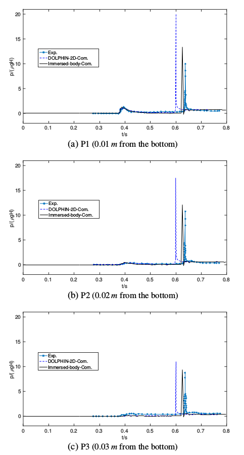
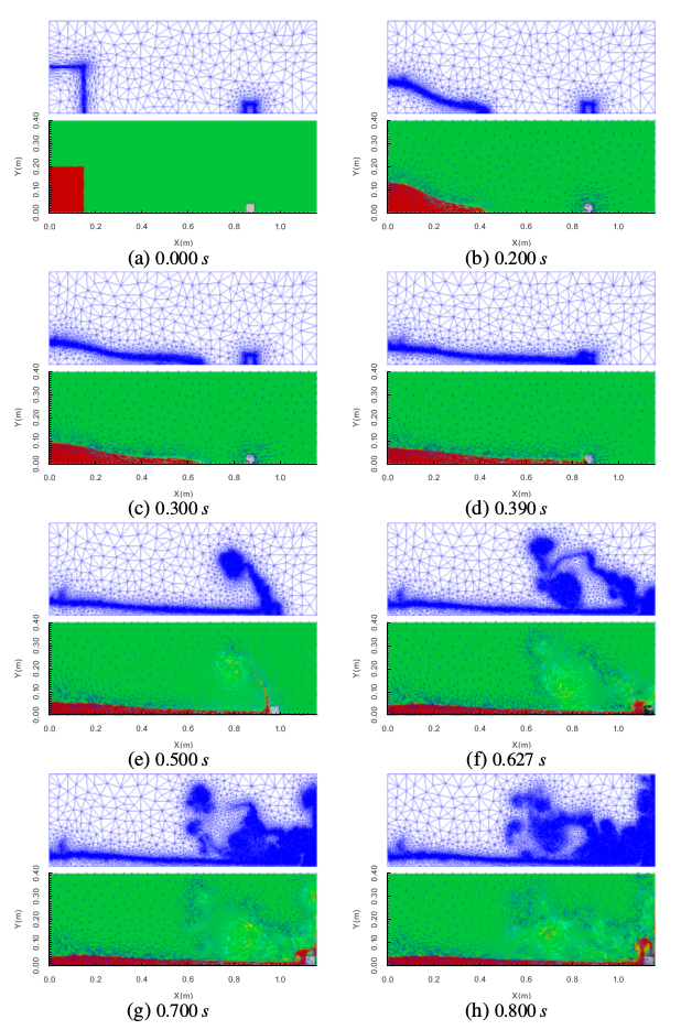
The numerical results of a collapsing column of water moving an initially stationary solid square were compared with the laboratory experiment data of Kawasaki and Mizutani (2007). This experiment demonstrated a collision between collapsing water and an initially stationary rigid solid square in an acrylic tank. The dimensions of the water tank are 1.15 m in length, 0.40 m in height and 0.20 m in width. There are two areas in the water tank, a reservoir and inundation area used to set a thin vertical gate. The initial water in the reservoir was set to 0.20 m in depth and 0.15 m in length. An initially stationary 0.04 m solid square was set at a distance of 0.70 cm from the front of the gate. In addition, there are three pressure gauges locating at 0.01 m, 0.02 m, and 0.03 m from the bottom, respectively. In this test case, the present results computed by the immersed-body method are in good agreement with the experimental one, see below. The first series of figures give the wave pressure acting on the initially stationary solid square. The black solid line represents the computational results of the immersed-body method in this paper. The blue dash line and asterisk line are simulation results and experimental data from Kawasaki and Mizutani (2007). P1, P2, and P3, refer to 0.01 m, 0.02 m, and 0.03 m from the bottom on the left surface of the initially stationary solid square impacted by the wave. The snapshot figures below are of a collapsing column of water moving an initially stationary solid square. The blue grids are the adapted meshes; the green parts refer to the air; the red parts represents the water; the blue vectors are the velocity vectors of the fluids; the white square is the solid square.
The immersed-body approach used in combination with adaptive mesh methods aretherefore considered a powerful means to analyze and resolve dynamic solids behaviour in solids (captured by Solidity) coupled with multiphase viscous flows.
References
Farrell PE, Piggott MD, Pain CC, et al., 2009, Conservative interpolation between unstructured meshes via supermesh construction, Computer Methods in Applied Mechanics and Engineering, Vol: 198, Pages: 2632-2642, http://dx.doi.org/10.1016/j.cma.2009.03.004,
K. Kawasaki and N. Mizutani. Numerical simulation of bore-induced dynamic behavior of rigid body using 2-D multiphase flow numerical model. In Proceedings of International Conference on Coastal Structures, pages 1477–1488. World Scientific, 2007.
Yang P. et al., (2016) Modelling of fluid-structure interaction with multiphase viscous flows using an immersed-body method, J. Comput. Phys. (2016), http://dx.doi.org/10.1016/j.jcp.2016.05.035.